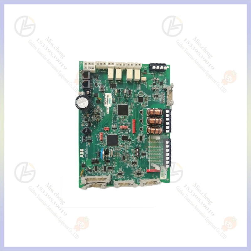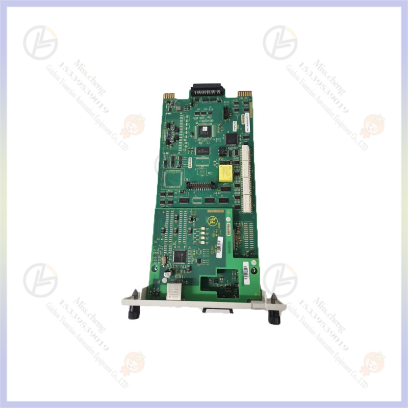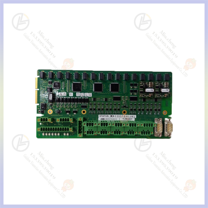


Brand:ABB
Product ID:DSAI130K01
Place of Origin:
Warranty: 365 days
Goods status: new/used
Mail: 3598571032@qq.com
Phone/Wechat/Whatsapp:+86 15339539190
Product details
Brand | ABB |
| Model | DSAI130K01 |
DSAI 130D Analog Input Board
16 inputs with 4 sets of filter times, 12 bit, Diff Input
+/-10V, +/-10MA, 0.03%
CONV.TIME 20 MS
CUT OFF FREQ. 10HZ,30HZ
100HZ,300HZ
The working principle of the analog input board is to filter out the high audio and clutter components in the audio signal and add the DC component that controls the maximum carrier power output of the transmitter, and optimize the audio signal, and finally output a composite signal of "audio + DC +72kHz jitter signal". And provide a sample signal of "audio + DC" for the DC stabilizer as the control signal of the B-power supply.
The circuit is used to set and adjust the maximum carrier power output of the transmitter, and control the corresponding level of power output or lifting, power, and power automatic compensation and blocking functions.1. Maximum carrier power setting circuitThe circuit is used for the synthesis of audio signal and DC signal, and outputs the composite signal of "audio + DC". The DC component determines the maximum carrier power of the transmitter, and the audio component determines the modulation system.The input audio signal is partialized (which can be detected on XJ1). When 100% modulation is added, the signal amplitude is 1.5Vp-p, without DC component), into N7A, after buffered amplification to the reverse phase input of N7B,-15V is regulated by the voltage regulator VD6 by R26, R27, R28 voltage, will be a negative DC voltage to the N7B in phase input (potentiometer R27 can adjust the negative straight The size of the current voltage), the audio signal and this negative DC signal are differentially amplified by N7B to output a "- (audio + DC)" signal. When the maximum carrier power is set to 10kW, the DC component of this "-(audio + DC)" signal is -1.5V, and when 100% modulation is added, the peak-to-peak value of its audio component is -3V (which can be detected on the XJ4).2. Digital output power control circuitWhen the transmitter executes startup, RF power output, conversion of different power levels and power rise and fall instructions, it can be realized through the digital output power control circuit. The utility model comprises a power control data latching circuit and a numerical control attenuator.
ABB series of products
| DSBB175 | DSDI110AK02 |
| DSBC172 | DSDI110AK10 |
| DSBC173 | DSDI110AK13 |
| DSBC174 | DSDI110AK14 |
| DSBC174K11 | DSDI110AK16 |
| DSBC174K12 | DSDI110AK17 |


+86 15339539190


